MBN-Company
MBN-Company
MBN-Company
MBN-Company
MBN-Company
MBN-Company
MBN-Company
MBN-Company
Information of news
  • Views: 212
  • Author: mbncom
  • Date:

Simple Steps in the Electronic Assembly

Category: News

Electronic assembly is the process of taking a PBC or printed circuit board and turning it into a PCBA or a printed circuit board assembly. This is done by connecting electrical components onto the circuit board. There are many small circuits that connect electricity in different intensities and different frequencies from point A to point B.  After the electronic assembly process, printed circuit board assemblies are used in many different There are 5 main steps in the electronic assembly process. 


Step 1: Printed Circuit Board 


In electronic assembly, you start with a printed circuit board and the components that go on it. The printed circuit board is a small board that looks something like this picture below. 


Step 2: Add Solder Paste


After you have your printed circuit board paste is applied to it using a screen-printer. A thin stencil is used so the paste only goes on the board in places where it is needed. 


Step 3: Pick-and-Place


Next, the components are placed on the circuit board. This is done by a machine called a Pick-and-Place that does exactly that, it picks them up and places them where they are supposed to be on the circuit board. Whatever the machine can’t do is done by hand by a technician. 


Step 4: Inspection 

After the components have been placed on the circuit board, it goes through an automated optical inspection process where it’s confirmed that everything is where it’s supposed to be, that it’s oriented correctly and that nothing is missing. 


Step 5: Soldering 

The step in the electronic assembly process is to put the PCBA in the oven. The oven melts the paste, which is made up of microbeads of metal. When the paste heats up in temperature, the metal melts and becomes one solid piece of connection. This connects components to the PCB. 

After Printed Circuit Board Assembly 

After the printed circuit board assembly process is completed and the components have been placed and soldered, the printed circuit board becomes much more functional. It can be used in any number of situations that require electrical parts from phones to cars. 

If you are looking for the right company to help in your next PCB assembly project, Implementing Ideas is the way to go. We specialize in having short turnaround times. The usual turnaround time for a PCB assembly project is anywhere from 8 to 12 weeks. With Implementing Ideas, you can plan on having a turnaround from a couple of days to a couple of weeks depending on the size of the project. Get started today here by getting a free quote. 

Information of news
  • Views: 217
  • Author: mbncom
  • Date:

Executing the Complete Power Generation Project

Category: News

In today’s climate of advanced environmental regulations and greater public awareness (or sometimes fear) of energy issues, the evaluation, planning, and permitting of new power plants are critical issues.

For a developer today to be successful, they must select the best technology and site, receive the required permits and construct the plant in a timely and cost-effective manner.

This article examines the most important issues of this process, with a particular focus on the most popular installations in the U.S., combined-cycle power generation plants. However, many of the topics apply to other methods of power generation including coal, stand-alone combustion turbines, biomass plants and others.


Steps 1 and 2

– Site and Technology Selection

Many variables must be clarified/determined during this phase of project development. These items include:

  • Targets for plant performance
  • Fuel source and availability
  • Fuel constituents and chemistry
  • Technology assessment
  • Project schedule
  • Geotechnical conditions
  • Makeup water source, chemistry, and treatment selection
  • Exhaust steam cooling – Cooling tower – Air-cooled condenser
  • Wastewater treatment selection
  • Interconnection logistics
  • Noise constraints

Some of these variables are easier to identify than others, but all need to be addressed very early in the project development cycle. The lack of timely decisions can significantly impact the overall project schedule. Owners today are being challenged with permitting and interconnection agreements that may take in excess of 12 months to complete. Lead times for major equipment acquisition are another schedule driver and will become a greater challenge as the global market for these products continues to grow. To help minimize the impact of equipment acquisition, a limited engineering release is necessary to begin procurement and preliminary design. Developers need a thorough understanding of the selected site prior to acquiring bids from engineering and construction firms, as this will greatly influence the final cost of the project. While much data exists in the public domain regarding subsurface conditions for many states and counties across the country, the data is often not specific enough to finalize costs and schedules. Often, a site investigation with only a handful of borings can give much insight, but a detailed study should be completed before design commencement or site activities.


With regard to equipment selection, a number of reputable and experienced vendors are available both nationally and globally to supply the major equipment plus the auxiliaries. Of course, the key selections include the combustion turbines, HRSGs, and steam turbine. However, auxiliary systems should not be overlooked by excessive focus on the major equipment. Important auxiliaries include transformers, makeup and cooling water equipment, auxiliary boilers, and instrumentation and control systems, to name several.

As the decision is made regarding the primary technology, thereupon comes development of heat and water balances. Modern programs incorporate specific data from the equipment chosen and will produce accurate calculations for many parameters including combustion turbine output, heat rate, steam production in the HRSGs, cooling tower performance and circulating water flow rate, among others. This data in turn allows refined calculations of water balances. Precision is paramount, as the water balance determines the required capacity of makeup water, and at times cooling water, treatment equipment. Undersizing of such equipment can lead to severe operating problems at and after startup, while oversizing adds significant cost to the system and may also result in poor performance. Another factor of importance is that a poor water balance can lead to installation of piping that is either too small or large for the application. Excel or a similar spreadsheet program is an excellent tool for preparing water balances, as water flow rates and usage can easily be calculated for any variety of conditions.


Once equipment selection has been finalized, the focus shifts to equipment layout. Some sites offer plenty of space for combustion turbine and auxiliary systems placement, but others may be very tightly constrained. One of the most significant factors for overall plant cost is quantities of commodities. Regardless of the space available, proper effort is needed to optimize the plant layout and in turn accurately calculate quantities and simplify construction. Factors that impact quantities include: piping and wiring locations and run lengths, steam turbine location, switchyard location, water treatment building placement, cooling tower location and many others.

It is important as a developer or utility to write the RFP in a manner that gives the EPC contractor flexibility regarding the plant layout. This is possible while still maintaining pre-established emission points included in air permit applications. As the equipment is being laid out two-dimensionally, designers also construct the model in 3D, which allows a much better analysis of pipe rack, cable tray and other overhead equipment locations. Development of the equipment arrangement expediently and with precision is also important for planning of of underground piping and electrical supplies. These need to be installed accurately upon the first attempt, as otherwise considerable time and effort may be expended in rerouting piping and cables after the fact.


All of these decisions factor into final technology selection. Besides power requirements, important aspects of combustion turbine selection include:

  • Fast start requirements
  • Planned startup/shutdown frequency
  • Emissions control
    – SCR system
    – CO catalyst
  • Possible water requirements
    – Compressor intercoolers
    – Water injection for NOx control

    These factors drive the choice of combustion turbine(s), including aeroderivative or frame units. The former offer very fast startups, but the heat rate is not as good as for frame units.

    Of course, for a combined-cycle plant the complexity increases. Additional equipment selection issues include:

    • HRSG details
      – Quantity
      – Width (2 bay vs. 3 bay)
      – Single- or multi-pressure
      • Steam turbine manufacturer
      • Makeup water treatment
      • Steam condensation technology
        – Cooling tower
        – Air-cooled condenser
        – Wet-surface air coolers
      • Wastewater discharge control

      The bulleted items above include reference to a critical aspect of power plant design, water/wastewater equipment selection and treatment. Author Buecker has covered many of these issues in recent issues of Power Engineering, but additional commentary regarding impending wastewater issues is provided in the section below.


      Step 3

      – Permitting

      As even many homeowners know, construction of simple buildings often requires one or more permits. The issue is vastly more complicated for power plant construction. Critical to the start of any project are air and water discharge permits, for if these are not requested early and contain very accurate information, the project will inevitably be delayed. As time passes, air permits continue to become more and more complex. In the past, permits were consistent regarding the pollutants to be regulated, and they were relatively specific and straightforward on reporting requirements. Permits today include strict limitations on startup and shutdown activities and may now include limitations on CO2 emissions. If permitting requirements are not clearly defined and matched to plant design, the owner could face operating limitations that significantly impact the profitability of the plant.


      Regarding water discharge, the guidelines are also becoming more complex. The EPA is preparing new National Pollutant Discharge Elimination System (NPDES) regulations. For many years, the primary impurities regulated by NPDES guidelines were pH, total suspended solids (TSS), oil & grease (O&G) and residual halogen (most typically chlorine or bromine). But now other items are appearing on the list, and not only from the USEPA but often from local or regional regulators. We are seeing limits for copper, zinc, ammonia, phosphate, sulfate and total dissolved solids (TDS). Undoubtedly, others will appear. This requires careful thought when it comes to deciding on selection of makeup and cooling water treatment, well ahead of equipment selection. Some experts now recommend zero liquid discharge installation for nearly every new project to avoid difficulties with additional regulations that most likely will occur in the future. But, ZLD is easier said than done. A final stream always remains from the primary process, and careful analysis, including additional permitting, is needed to determine whether the final product can be disposed in evaporation ponds, deep well injection, by off-site means, or by thermal evaporation. The upshot is that it is important to begin the permitting process very early on in a project, for final approval may take well over a year.


      Step 4

      – Construction

      Many projects we perform are of the engineer-procure-construct (EPC) type. Two critical items are important for starting a project correctly and taking it to a successful conclusion. These are:

      • Safety
      • Close contact with the owner throughout the project

      Bringing in the EPC contractor early in the development process helps with planning and constructability of the project. The engineering and construction team can identify potential safety risks related to construction or operations/maintainability of the plant.


      Step 5

      – Startup and Performance Testing

      As construction reaches completion, the startup and performance testing activities commence. These activities can be performed by the owner, the EPC contractor or a third party. In any event, it is critical to involve the startup and testing teams early such that coordination of the tests and testing equipment may be incorporated in the design and construction.

      Kiewit Power Engineers has been involved with countless project development and EPC projects. The time and effort owners put into making a project “shovel ready” is quite significant. By getting a jump on permitting and involving an EPC Contractor early, owners have a better chance of seeing the project up and running in the most expeditious amount of time.


Information of news
  • Views: 215
  • Author: mbncom
  • Date:

Hydraulic Systems and Fluid Selection

Category: News

It wasn’t until the beginning of the industrial revolution when a British mechanic named Joseph Bramah applied the principle of Pascal’s law in the development of the first hydraulic press. In 1795, he patented his hydraulic press, known as the Bramah press. Bramah figured that if a small force on a small area would create a proportionally larger force on a larger area, the only limit to the force that a machine can exert is the area to which the pressure is applied.

What is a Hydraulic System?

Hydraulic systems can be found today in a wide variety of applications, from small assembly processes to integrated steel and paper mill applications. Hydraulics enable the operator to accomplish significant work (lifting heavy loads, turning a shaft, drilling precision holes, etc.) with a minimum investment in mechanical linkage through the application of Pascal’s law, which states:

“Pressure applied to a confined fluid at any point is transmitted undiminished throughout the fluid in all directions and acts upon every part of the confining vessel at right angles to its interior surfaces and equally upon equal areas

By applying Pascal’s law and Brahma’s application of it, it is evident that an input force of 100 pounds on 10 square inches will develop a pressure of 10 pounds per square inch throughout the confined vessel. This pressure will support a 1000-pound weight if the area of the weight is 100 square inches.

The principle of Pascal’s law is realized in a hydraulic system by the hydraulic fluid that is used to transmit the energy from one point to another. Because hydraulic fluid is nearly incompressible, it is able to transmit power instantaneously.

Hydraulic System Components

The major components that make up a hydraulic system are the reservoir, pump, valve(s) and actuator(s) (motor, cylinder, etc.).

Reservoir
The purpose of the hydraulic reservoir is to hold a volume of fluid, transfer heat from the system, allow solid contaminants to settle and facilitate the release of air and moisture from the fluid.

Pump
The hydraulic pump transmits mechanical energy into hydraulic energy. This is done by the movement of fluid which is the transmission medium. There are several types of hydraulic pumps including gear, vane and piston. All of these pumps have different subtypes intended for specific applications such as a bent-axis piston pump or a variable displacement vane pump. All hydraulic pumps work on the same principle, which is to displace fluid volume against a resistant load or pressure.

Valves
Hydraulic valves are used in a system to start, stop and direct fluid flow. Hydraulic valves are made up of poppets or spools and can be actuated by means of pneumatic, hydraulic, electrical, manual or mechanical means.

Actuators
Hydraulic actuators are the end result of Pascal’s law. This is where the hydraulic energy is converted back to mechanical energy. This can be done through use of a hydraulic cylinder which converts hydraulic energy into linear motion and work, or a hydraulic motor which converts hydraulic energy into rotary motion and work. As with hydraulic pumps, hydraulic cylinders and hydraulic motors have several different subtypes, each intended for specific design applications.


سیستم های هیدرولیک - تجهیزات صنعتی - مدیران بهینه ساز نصیر- Hydraulic system-electrical

www.mbncompany.com


Information of news
  • Views: 191
  • Author: mbncom
  • Date:

Maintenance of Devices and Instrumemnts tips

Category: News

Maintaining Electrical Outlets Keeps Employees and Work Environments Safe


Maintaining Electrical Outlets Keeps Employees and Work Environments Safe


Damaged or worn electrical outlets can cause injuries, like electrocution, and fires in

commercial or industrial settings. Below are some signs that your outlets may be damaged, and their avoidable causes.

Loose Plugs:
When inserting a plug, it should feel snug -- not tight or overly loose. This could be a sign of outlet wear, or misuse when unplugging devices (always unplug from the grip, don’t pull on the cord).

Cracked or Warm Outlets:
If an outlet is cracked, or if it feels warm to the touch, it should be inspected by an electrical expert . This is often an indicator that it was improperly wired, or that the wiring may have been damaged -- a common cause of electrical fires. It can also mean the spring tension inside the receptacle has worn down and is in need of replacement.

Testing Ground Fault Circuit Interrupters:
Ground Fault Circuit Interrupters (GFCI) outlets are required by electrical code in areas where water may come into contact with the outlet. If water comes into contact with the outlet, the GFCI will trip, cutting the electrical connection and avoiding electrocution. You can test the GFCI by pushing the button -- anything plugged in should turn off immediately. If it doesn’t, call a qualified technision.

Using Surge Protectors:
Most offices and other commercial facilities use surge protector power strips for their computers, to connect and protect a number of extra devices such as printers, phones, etc. from sudden surges of electricity, which can destroy expensive and critical electronic equipment. Surge protector outlets are now available to install directly into a wall.

There are three levels of surge protection normally used. Service, panel and load (outlets and power strips). The best course of action is to apply all three levels, but for starters, the service is the best place to help keep the surge from entering a building.

Electrical Equipment Inspections Keep You Up to Code

During your annual maintenance checkups, remember to check equipment including:

  • Local disconnects for machines and equipment.
  • Electrical panels.
  • Batteries on battery-powered equipment.
  • Wiring terminations in equipment subject to vibration.
  • Cord and plug connected equipment.
  • Other miscellaneous compromised electrical components such as broken or disconnected conduits, and flexible connections.

Check each of these items for cracks, deterioration, or corrosion. Clear the areas near them of dust and other debris that could cause potential equipment failure or hinder access for your electrical maintenance technician. Remember to turn off power to the machines, wiring, or other equipment before cleaning or performing any type of maintenance.

It’s important to pay attention to performance issues like flickering lights, spontaneously low power, or odd equipment resets. Employee feedback and notes about equipment performance should be considered in any equipment testing and inspection since they’re the people most likely to notice the small electrical hiccups that could be a sign of a failing part or a malfunctioning connection.

During your EPM work, it is a good time to check if your existing installations are up to code. Making these repairs before they become a problem will be another way to keep from unnecessary down-time or failed inspections.

Lighting Inspections Improve Productivity


Service_Projects-Alternate_blogEven the most expensive lighting fixtures and lamps will require maintenance and eventually dim, then burn out. This can be problematic, as studies show that better lighting leads to more productivity in the workplace -- meanwhile, poor lighting makes it harder for employees to focus on the objects in front of them, or distinguishing objects from the background.

Be sure to check your exit and emergency lights. Fire and Building inspectors look for these issues during routine inspections. Keeping on top of their functionality will keep you out of their spotlight. These lights are part of your emergency egress system and are critical to guide people out of the building in the event of an emergency.

Lighting is responsible for most of the single-user electrical energy use in commercial and industrial buildings. Well maintained lighting is important for several reasons:

  • Clearer visibility means better safety.
  • Strong lighting improves productivity.
  • Maintained lighting fixtures are more energy efficient.

Another important consideration is lamp lumen depreciation (LLD) —- this is when your lighting fixture loses power and dims over time. Check lighting strength and replace dimmed lights during your regularly scheduled maintenance.

Additionally, your checklist should take luminaire dirt depreciation (LDD) into account. Some lamps and fixtures are more vulnerable to dirt and dust buildup, which causes the light fixture to emit less light. Lighting fixtures should be cleaned regularly as well.

As you inspect your lighting, be aware of areas where LED replacement lighting could create a safer, healthier or more productive workspace. Your electrician can help identify areas for improvement. LED lighting will also save energy and energy costs.


Information of news
  • Views: 210
  • Author: mbncom
  • Date:

List of Mechanical Properties of Materials

Category: News

The mechanical properties of materials define the behavior of materials under the action of external forces called loads.

There are a measure of strength and lasting characteristics of the material in service and are of good importance in the design of tools, machines, and structures.

The mechanical properties of metals are determined by the range of usefulness of the metal and establish the service that is expected.

Mechanical properties are also useful for helping to specify and identify metals. And the most common properties considered are strength, hardness, ductility, brittleness, toughness, stiffness, and impact resistance.

List of Mechanical Properties of Materials

The following are the mechanical properties of materials.

  1. Strength
  2. Elasticity
  3. Plasticity
  4. Hardness
  5. Toughness
  6. Brittleness
  7. Stiffness
  8. Ductility
  9. Malleability
  10. Cohesion
  11. Impact strength
  12. Fatigue
  13. Creep
Information of news
  • Views: 263
  • Author: mbncom
  • Date:

Electrical Panel

Category: News

What is an electrical panel?

The electrical panel is the main component of an electrical distribution system that divides electrical power to the branch circuits while providing protection devices for each circuit in a common enclosure.

In essence, electrical panels are used to protect against electrical overloads and short circuits while distributing electricity throughout a building or facility.

The National Electrical Code® (NEC®) defines an electrical panel as a single panel or group of panel units designed for assembly in the form of a single panel; including buses, automatic overcurrent devices, and equipped with or without switches for the control of light, heat, or power circuits; designed to be placed in a cabinet or cutout box placed in or against a wall or partition and accessible only from the front

According to the NEC® definition, electrical panels are:

  • Used to control light, heat, or power circuits
  • Placed in a cabinet or cutout box
  • Mounted in or against a wall
  • Accessible only from the front

Other definitions of the electrical panel:

  • Panelboard
  • Distribution board
  • Electrical switchboard

Electrical panel types

Electrical panels are often categorized by their general application, whether they are used for lighting and appliances or used for power. There are 4 types of panels available: Lighting electrical panels, power electrical panels, switchboards, low voltage switchgear.

Lighting electrical panels

Lighting and appliance electrical panels contain overcurrent protection and a means to disconnect lighting, appliances, receptacles, and other small load circuits. All other electrical panels are used for power and may also feed other panels, motors, and transformers in the building’s or site’s overall power distribution systems.


Power electrical panels

Power electrical panels are generally used in industrial facilities and new or retrofit commercial construction applications where the electrical distribution needs are more complex and require system-level solutions. These electrical panels offer broad system application capability for service entrance requirements or general power circuit distribution. For example, multi-tenant use facilities commonly employ power panelboards for electrical distribution. Increasingly, power electrical panels are specifically designed to meet applications where changes and additions must be fast, convenient, and easy.

Today’s innovative power electrical boards enable facilities to achieve reliable power performance at optimal energy-efficiency levels within the smallest footprint possible. The primary benefits of power electrical panels are their ability to accommodate wider ranges of volts AC while housing more breakers in less space. Both circuit breakers and fusible switches can be included in a single, bolt-on chassis design. A variety of special power electrical panel features enable facility managers to coordinate power distribution selectively, meter and monitor power usage closely and remotely, and ensure personnel safety with arc flash and fault protection options.


Switchboards

For larger-scale buildings or sites, a large single panel, frame, or assembly of panels can be used for mounting the overcurrent switches and protective devices, buses, and other equipment. These floor-mounted, freestanding solutions are known as switchboards.

Switchboards are most often accessible from the front, mounted on the floor, and close to the wall. Switchboards function the same as panelboards (and often simply feed other panelboards), but on a larger scale and at the low voltage of 600 Vac or less. They are used to divide large blocks of electrical current into smaller blocks used by electrical devices. This division helps distribute power to loads; disconnecting loads for safer maintenance; and protecting conductors and equipment against excess current due to overloads, short circuits, and ground faults.

Generally, switchgear should be considered whenever the highest degree of power reliability is desired. It is especially appropriate for critical power applications—those that are so important to a user’s enterprise that they cannot sustain a loss of power without incurring a harmful loss of revenue, production, or human safety.


Electrical devices inside the electrical panel

Although it varies according to the type of panel, when you open a panel door you are likely to see the following elements:

  • Circuit breakers
  • Disconnectors
  • Contactors
  • Miniature circuit breakers
  • Surge protection devices
  • Terminal blocks
  • Residual current devices
  • Cable ferrules, cable ducts, cable ties
  • Cables
  • Motor protection devices
  • Thermal overload relays
  • Relays
  • PLCs
  • Power supplies
  • HMI
  • Pilot devices
  • Power capacitors
  • Measurement and display devices mounted on the panel cover
  • Current and voltage transformers
  • Limit switches
  • Panel heaters
  • Panel fans
  • Thermostats
Information of news
  • Views: 329
  • Author: mbncom
  • Date:

Electrical panels

Category: News

What is an electrical panel?

An electrical panel (a.k.a. breaker panel) is a metal box with a door, usually built into a wall in an out-of-the-way corner of your home. Inside, you’ll find all your home’s breaker switches.

You can toggle breaker switches on and off. They’ll also shut off automatically when there’s too much electrical current running through them — that’s what they’re for.

Within the electrical panel, you’ll find a main circuit breaker that controls the power to the entire house. You’ll also see individual breakers, each responsible for providing the electricity to a specific part of your home. Each breaker should have a label that identifies the area of the house it controls.

Some older homes don’t have breakers; they have fuses instead. If you have a fuse box, you won’t see any switches on your electrical panel; you’ll see screw-in fuses. If your home still uses a fuse box, you may have difficulty getting insurance, or you may have to pay a higher rate. We’ll address fuses and home insurance further down the page.

The power to your home comes through an electrical meter outside, which routes power to your electrical panel. You can shut off this main feed of electricity using the main breaker in your electrical panel. Your main breaker also tells you the amperage of your electrical service (amperage is the strength of the electrical current).

Home electric services in Canada range from 60 to 400 amps. Most electrical codes mandate at least 100-amp service.

Home insurance providers are often interested in your home’s amperage. If it’s less than 100, you might need to update your system. Sub-100 amperage could make it difficult for you to find insurance for your home; at the very least, you’ll need to pay a higher rate.


How to locate your panel

Electrical panels are metal boxes, typically grey in colour. They’re usually embedded in a wall.

Electrical panels have doors (or at least, they should). Behind the door, you’ll find an assortment of wires and switches — those switches are your breakers.

Electrical panels are normally in an out-of-the-way part of your home. Basements, storage rooms, laundry rooms, or garages are all common places to install an electrical panel. In older homes, you might even have to look outside the house to find your panel.

If you live in an apartment, you’ll usually find your electrical panel right next to the entrance to your unit.

Most homes have just one electrical panel, though some may have subpanels, especially homes that have multiple living units. See the common questions section for more on subpanels.


How does an electrical panel work?

Circuit breakers trip (that is, shut off) when the circuit is overloaded. They’re safety devices, meant to prevent damage to electrical devices or to the home itself. If the breaker didn’t trip and shut off the power, overloaded circuits could start fires or electrocute someone.

Each breaker controls one circuit; each circuit usually corresponds to a room or an area of the house. Power-hungry devices like electric ranges or air conditioners might have their own breaker.

A breaker is designed to carry a certain electrical load; if the electrical load grows too large for the breaker, it shuts off. This happens if you have too many devices plugged into one circuit, for example.

There are assorted sizes of breakers depending on how much electricity they need to handle. Like the home’s electrical service, individual breakers are divided by what amperage they can handle. Breakers range from 15 to 200 amps; most are either 15, 20, or 30 amps, though.

Breakers also have voltage ratings; a single circuit breaker is normally provides 120 volts — the typical amount needed for lights, TVs, etc. A double circuit breaker is rated for 240 volts. This is for the big appliances that draw a lot of power, such as a stove or electric dryer.

When the breaker trips, all you need to do is flip the switch to reset it. In older homes with fuse boxes, you can’t just reset it; you need to replace the whole fuse if it blows.

How much does it cost to change or upgrade an electrical panel?

The cost to upgrade your home’s electrical panel varies widely depending on the scope of the work, but you should expect to pay (very roughly) $2,000 – $2,500. That’s for 100-amp service; the price will be higher if you need to rewire your home for 200+ amps.

The only way to be sure about the cost is to have an electrician (or better yet: 3 different electricians) give you detailed quotes.

There are two reasons you’d want to upgrade your electrical panel: your service doesn’t provide enough power for your home, or you have fuses instead of breakers.

If your home has a fuse box, or your electrical service is below 100 amps, you should upgrade. Even if you already have 100-amp service, you might need to upgrade to 200- or 400-amp service, as many homes are running at capacity on 100-amp service.

If you’re not sure your electrical panel is enough, you can have an electrician estimate your service usage and tell you if you need an upgrade or not.

Electric Code Circuit Breaker Panel Box Requirements

Building codes govern electrical panels. For safety reasons, panels need to adhere to many standard requirements.

Building codes in Canada are different in each province and municipality, but generally speaking, they dictate:

  • The height at which the breaker box must be.
  • The location of the breaker box within the house. For example, they can’t be in a bathroom.
  • The accessibility of the breaker box. As in, the box can’t be behind a bookshelf, and always must have clear space to open the panel door.
  • The breakers must be clearly labelled. That includes their amperage ratings and which parts of they house they control.

There are tons of other technical electric code requirements for breaker boxes. But, unless you’re an electrician, you don’t need to worry; work on breaker boxes and electrical wiring should always be done by a qualified person.


Electrical panekElectrical panek


www.mbncompany.com


Information of news
  • Views: 266
  • Author: mbncom
  • Date:

Condition Monitoring Techniques

Category: News

Complete List of Condition Monitoring Techniques

The future holds great promise for condition monitoring as more sensors are developed that can be mounted on equipment. Also, more equipment is being built to Internet of Things (IoT) standards.

Kelvin Bui, Marketing Associate at SMC, in the MSI Data blog said, “Industrial devices now have an unprecedented amount of sensing, processing and communications capabilities built into the product itself.”

Data analyzed for condition monitoring serves as the basis for predictive maintenance. Patterns emerge from the data showing a machine part may be deteriorating or beginning to fail. Based on the analysis, maintenance is then scheduled to prevent failure and avoid emergency downtime.

The following list of condition monitoring techniques, grouped by several category types, shows the extent technology has moved monitoring ahead. The various methods listed may or may not currently be linked within an IoT network, but most are suitable for automatic data collection and analysis.


Oil Analysis/Tribology
This technique involves collecting and testing machine oils, equipment lubricants or other fluid samples to ascertain the condition of either/both the fluids and the machines. As machines wear, overheat or trend toward failure, contaminants are deposited in lubricating oils and other operating fluids. Careful analysis of oil samples reveals these contaminants. Data from these studies can then be interpreted to indicate impending failures.

Techniques include:
• Ferrography
• Presence of water
• Viscosity/kinematic viscosity test
• ICP or atomic emissions spectroscopy to identify presence of contaminants
• Dielectric strength test
• Microbial analysis
• Particle quantification index (iron content)
• Fourier transform infrared spectroscopy
• Ultraviolet spectroscopy
• Potentiometric titration/total acid number and total base number
• Sediment test

Vibration Analysis/Dynamic Monitoring
Equipment and parts respond to vibrations in a variety of ways that can be used to identify defects due to misalignments, imbalances or design flaws. Wear on machine parts, bearings, rotors and shafts, causes these parts to vibrate with specific patterns that can be recorded and analyzed. Different parts vibrate in different ways, and worn or out-of-balance parts have unique vibration signatures that can be tracked and used to predict parts failures.

Techniques include:
• Shock pulse analysis
• Fast fourier transforms
• Broadband vibration analysis
• Ultrasonic analysis
• Power spectral density (PSD)
• Time waveform analysis
• Spectrogram/spectrum analysis

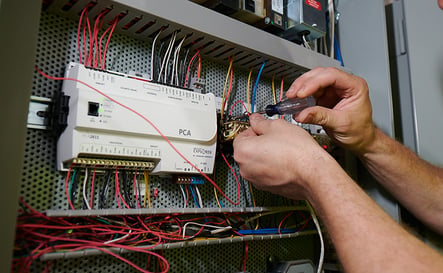
Motor Circuit Analysis
Motor circuit analysis (MCA) is a battery of computerized tests on an electric motor to ascertain the motor’s overall condition and possible sources of potential failures. Electrical imbalances and degradation of insulation are the chief causes of motor failure and are the focus of MCA testing.

Some tests are go/no-go tests, while test results for others must be tracked over time to identify failure development. These tests are generally grouped into voltage-based or current-based tests.

Inspection points include:
• Power circuit/current signature
• Online and offline testing (not tests but testing regimes)
• Rotor
• Stator
• Insulation
• Power quality
• Air gap

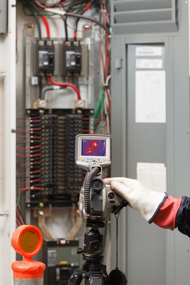
Thermography/Temperature Measurements/Infrared Thermography
Thermography is the study of heat patterns in machines and objects. Images capture thermal radiation patterns emitted from equipment. Data analysis is used to identify potential failures or degradation of equipment parts. Generally, equipment and parts will heat as parts failure is developing. Thermal anomalies and temperature differences can indicate misalignment, imbalances, improper lubrication, worn components, undesirable mechanical stresses and electrical overheating.

Thermographic inspection helps identify safety issues such as overheated electrical connections, pipe leaks and pressure vessel weaknesses. Many infrared techniques based on the principles of IR radiation have been developed to fit specific industrial applications.

Techniques include:
• Comparative thermography
• Testing of electrical, pipe-works and machinery
• Comparative quantitative thermography
• Comparative qualitative thermography
• Paint stickers (colour change with out of spec temperatures)
• Fluids that change colour at out-of-spec temperatures
• Lock-in thermometry
• Pulse phase thermometry
• Pulse thermometry

Ultrasonic Monitoring/Acoustic Analysis/Airborne Ultrasonics
Ultrasonic monitoring of equipment, bearings and rotating parts uses high-frequency sound waves to detect part defects such as leaks, parts seating and cavitations. In many cases, tiny changes in friction forces can be detected with ultrasonic monitoring. These small changes may be missed with IR or vibration analysis. Because of this, UM can be an excellent companion testing technique along with IR and vibration analysis.

Almost all areas of manufacturing processes can benefit from ultrasonic monitoring UM. It provides an early warning for machine parts deterioration that might otherwise be masked by ambient plant noises and temperatures.

Techniques include:
• Airborne ultrasonics
• Ultrasonic backscatter technique
• Backwall echo attenuation
• Ultrasonic thickness and gauging (pipe walls, etc.)
• Phased array testing
• Automatic and continuous ultrasonic inspection
• Internal rotating inspection systems
• Acoustic emissions testing
• Dry-coupled ultrasonic testing
• Long-range ultrasonic testing
• Acoustic ranging
• Time-of-flight diffraction

Radiography/Radiation Analysis/Neutron Radiography
This method uses radiation imaging to identify internal defects in equipment and parts. Applications include inspection of weldments, castings and sintered parts. This approach is one of the most thorough methods of non-destructive testing available.

The technique is based on measuring the differential absorption of radiation penetrating the part or material. Internal corrosion and flaws absorb differing amounts of radiation, which can be measured and analyzed.

Techniques include:
• Neutron backscatter
• Computed radiography
• Computed tomography (CT)
• Direct radiography
• Positive material identification (PMI)
• Neutron radiography

Laser Interferometry
Laser interferometry measures changes in wave displacement based on a laser-generated, highly accurate wavelength of light. This technique is used to identify surface and subsurface defects in composites and other materials. It is based on the interference of light waves generated by a laser. (Sound and radio/electromagnetic waves are also used.) The interference pattern is then captured and measured by a device called an interferometer.

The various interference patterns can be analyzed to show differences in material characteristics such as the presence of corrosion, surface defects or cavities in the material.

Techniques include:
• Laser shearography
• Laser ultrasonics
• Strain mapping
• Electronic speckle pattern interferometry
• Digital holography (used worldwide to test turbine blades and surgical parts)
• Holographic interferometry (still in laboratory testing/not currently used in general widespread condition monitoring)

Electrical Monitoring
This approach applies the principles of deviations in electrical parameters to identify faults and defects. Characteristics such as resistance, induction, capacitance, pulse response, frequency response and others are used to detect potential maintenance issues. Central to this methodology is the measurement of degradation trends in an electrical system so that preventative action can be taken in advance of any system failure.

Techniques include:
• Megohmmeter testing
• High potential testing
• Power signature analysis
• Battery impedance testing
• Surge testing
• Motor circuit analysis
• Alternating current field measurement (ACFM)

Electromagnetic Measurement
This category of test measures magnetic field distortions and eddy current changes to identify cracks, corrosion, weaknesses and other defects. A magnetic field is applied to surface walls, setting up magnetic fields. These fields interfere with one another causing patterns. Eddy current reporting over an extended period is used to identify gradual deterioration in material quality and surface features.

Similarly, electromagnetic testing induces an electromagnetic field or electric current inside the tubing or test object. Defects will create disturbances, which can be measured and analyzed. A variety of techniques have been developed to take advantage of these properties.

Techniques include:
• Magnetic particle inspection
• Magnetic flux leakage
• Metal magnetic memory method
• Pulsed eddy currents
• Remote and near field eddy current
• Saturated low-frequency eddy currents
• Other eddy current testing

Performance Monitoring/Observation and Surveillance/Process Variable and Performance Trending
This traditional approach to monitoring production equipment uses visual inspection and physical senses to judge the proper functioning of a piece of machinery. The technique also uses tracking of output and manufacturing performance to identify deviations in expected results. When production output changes, defects increase or physical characteristics noticeably vary from the norm (sound, heat, vibration), these changes may indicate problems with equipment and possible failures.

This method of monitoring equipment is a valuable technique where advanced technological testing methods are not available. Much of the interpretation of results depends on careful record keeping and interpretation and application of hands-on experience.

Techniques include:
• Visual inspection
• Audio inspection
• Flow rates
• Touch inspection
• Temperatures
• Pressures
• Output or performance trends
• Downtime analysis

Is this everything?
Probably not, but a majority of known condition monitoring techniques you can find on the market today were covered. As industry moves closer and closer to adopting IoT, the practice of condition monitoring is becoming more critical.

Sensors now allow machines to communicate their condition through the Internet to central databases. Newly created analytics then analyze this data to identify which machine parts may be starting to fail. The condition of the equipment can be monitored in real time so that you can schedule planned downtime and proactive maintenance to prevent costly equipment failures.


ِCondition monitoring

www.mbncompany.com


Information of news
  • Views: 230
  • Author: mbncom
  • Date:

The history of electronics

Category: News

The history of electronics

Theoretical and experimental studies of electricity during the 18th and 19th centuries led to the development of the first electrical machines and the beginning of the


widespread use of electricity. The history of electronics began to evolve separately from that of electricity late in the 19th century with the identification of the electron by the English physicist Sir Joseph John Thomson and the measurement of its electric charge by the American physicist Robert A. Millikan in 1909.


At the time of Thomson’s work, the American inventor Thomas A. Edison had observed a bluish glow in some of his early lightbulbs under certain conditions and found that a current would flow from one electrode in the lamp to another if the second one (anode) were made positively charged with respect to the first (cathode). Work by Thomson and his students and by the English engineer John Ambrose Fleming revealed that this so-called Edison effect was the result of the emission of electrons from the cathode, the hot filament in the lamp. The motion of the electrons to the anode, a metal plate, constituted an electric current that would not exist if the anode were negatively charged.


This discovery provided impetus for the development of electron tubes, including an improved X-ray tube by the American engineer William D. Coolidge and Fleming’s thermionic valve (a two-electrode vacuum tube) for use in radio receivers. The detection of a radio signal, which is a very high-frequency alternating current (AC), requires that the signal be rectified; i.e., the alternating current must be converted into a direct current (DC) by a device that conducts only when the signal has one polarity but not when it has the other—precisely what Fleming’s valve (patented in 1904) did. Previously, radio signals were detected by various empirically developed devices such as the “cat whisker” detector, which was composed of a fine wire (the whisker) in delicate contact with the surface of a natural crystal of lead sulfide (galena) or some other semiconductor material. These devices were undependable, lacked sufficient sensitivity, and required constant adjustment of the whisker-to-crystal contact to produce the desired result. Yet these were the forerunners of today’s solid-state devices. The fact that crystal rectifiers worked at all encouraged scientists to continue studying them and gradually to obtain the fundamental understanding of the electrical properties of semiconducting materials necessary to permit the invention of the transistor.


In 1906 Lee De Forest, an American engineer, developed a type of vacuum tube that was capable of amplifying radio signals. De Forest added a grid of fine wire between the cathode and anode of the two-electrode thermionic valve constructed by Fleming. The new device, which De Forest dubbed the Audion (patented in 1907), was thus a three-electrode vacuum tube. In operation, the anode in such a vacuum tube is given a positive potential (positively biased) with respect to the cathode, while the grid is negatively biased. A large negative bias on the grid prevents any electrons emitted from the cathode from reaching the anode; however, because the grid is largely open space, a less negative bias permits some electrons to pass through it and reach the anode. Small variations in the grid potential can thus control large amounts of anode current.


The vacuum tube permitted the development of radio broadcasting, long-distance telephony, television, and the first electronic digital computers. These early electronic computers were, in fact, the largest vacuum-tube systems ever built. Perhaps the best-known representative is the ENIAC (Electronic Numerical Integrator and Computer), completed in 1946.

The special requirements of the many different applications of vacuum tubes led to numerous improvements, enabling them to handle large amounts of power, operate at very high frequencies, have greater than average reliability, or be made very compact (the size of a thimble). The cathode-ray tube, originally developed for displaying electrical waveforms on a screen for engineering measurements, evolved into the television picture tube. Such tubes operate by forming the electrons emitted from the cathode into a thin beam that impinges on a fluorescent screen at the end of the tube. The screen emits light that can be viewed from outside the tube. Deflecting the electron beam causes patterns of light to be produced on the screen, creating the desired optical images.


Notwithstanding the remarkable success of solid-state devices in most electronic applications, there are certain specialized functions that only vacuum tubes can perform. These usually involve operation at extremes of power or frequency.

Vacuum tubes are fragile and ultimately wear out in service. Failure occurs in normal usage either from the effects of repeated heating and cooling as equipment is switched on and off (thermal fatigue), which ultimately causes a physical fracture in some part of the interior structure of the tube, or from degradation of the properties of the cathode by residual gases in the tube. Vacuum tubes also take time (from a few seconds to several minutes) to “warm up” to operating temperature—an inconvenience at best and in some cases a serious limitation to their use. These shortcomings motivated scientists at Bell Laboratories to seek an alternative to the vacuum tube and led to the development of the transistor.


electronic

www.mbncompany.com


Information of news
  • Views: 0
  • Author: mbncom
  • Date:

What is a transformer and how does it work?

Category: News

What is a transformer and how does it work?

A transformer is an electrical apparatus designed to convert alternating current from one voltage to another. It can be designed to "step up" or "step down" voltages and works on the magnetic induction principle. A transformer has no moving parts and is a completely static solid state device, which insures, under normal operating conditions, a long and trouble-free life. It consists, in its simplest form, of two or more coils of insulated wire wound on a laminated steel core. When voltage is introduced to one coil, called the primary, it magnetizes the iron core. A voltage is then induced in the other coil, called the secondary or output coil. The change of voltage (or voltage ratio) between the primary and secondary depends on the turns ratio of the two coils.


What are taps and when are they used?

Taps are provided on some transformers on the high voltage winding to correct for high or low voltage conditions, and still deliver full rated output voltages at the secondary terminals. Standard tap arrangements are at two and one-half and five percent of the rated primary voltage for both high and low voltage conditions. For example, if the transformer has a 480 volt primary and the available fine voltage is running at 504 volts, the primary should be connected to the 5% tap above normal in order that the secondary voltage be maintained at the proper rating. The standard ASA and NEMA designation for taps are "ANFC" (above normal full capacity) and "BNFC" (below normal full capacity).


What is the difference between "Insulating", "Isolating", and "Shielded Winding" transformers?

Insulating and isolating transformers are identical. These terms are used to describe the isolation of the primary and secondary windings, or insulation between the two. A shielded transformer is designed with a metallic shield between the primary and secondary windings to attenuate transient noise. This is especially important in critical applications such as computers, process controllers and many other microprocessor controlled devices. All two, three and four winding transformers are of the insulating or isolating types. Only autotransformers, whose primary and secondary are connected to each other electrically, are not of the insulating or isolating variety.


Can transformers be operated at voltages other than nameplate voltages?

In some cases, transformers can be operated at voltages below the nameplate rated voltage. In NO case should a transformer be operated at a voltage in excess of its nameplate rating unless taps are provided for this purpose. When operating below the rated voltage the KVA capacity is reduced correspondingly. For example, if a 480 volt primary transformer with a 240 volt secondary is operated at 240 volts, the secondary voltage is reduced to 120 volts. If the transformer was originally rated 10 KVA, the reduced rating would be 5 KVA, or in direct proportion to the applied voltage.


How do you select transformers?

1. Determine primary voltage and frequency. 2. Determine secondary voltage required. 3. Determine the capacity required in volt-amperes. This is done by multiplying the load current (amperes) by the load voltage (volts) for single phase. For example: if the load is 40 amperes, such as a motor, and the secondary voltage is 240 volts, then 240 x 40 equals 9600 VA A 10 KVA (10,000 volt-amperes) transformer is required. ALWAYS SELECT THE TRANSFORMER LARGER THAN THE ACTUAL LOAD. This is done for safety purposes and allows for expansion, in case more load is added at a later date. For 3 phase KVA, multiply rated volts x load amps x 1.73 (square root of 3) then divide by 1000. 4. Determine whether taps are required. Taps are usually specified on larger transformers. 5. Use the selection charts in the Acme catalog.


Related Posts :

    Contact Us :

    Headquarter: Unit:15-No:12-Gandhi 19-Gandhi Blv-Tehran-Iran
    Postal Code: 1517874438
    Telephones: (+98-21)44237763 (+98-21)88668972 (+98-21)88663258
    Fax NO: (+98-21)89770683
    E-mail : Info@mbncompany.com
    Laboratory and instrumentation section: mbnasir.co@gmail.com
    Electrical section: mbnco@outlook.com
    After sales section: support@mbncompany.com

    Google Map :


    سئو | کاشت مو | صندلی پلاستیکی | بادکنک آرایی